Electric Control line
This website is hosted by CrazyHostingSA and I can really recommend them.
Just click on the name if you want to know more.
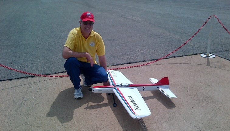
Keith with Newtron
Please Note: I can process overseas orders now using PayPal. Click HERE to go to orders.
The overseas prices in US Dollars are below in blue colour. I have worked them out to cover costs of foreign exchange and also PayPal charges. Please note that I cannot use credit cards. PayPal is reliable and works well.
At present I am using OCS Global Mail and this seems to be working well. The parcel only weighs about 25 grams and I send it in a padded envelope. This takes about 5 working days to the UK, and 11 days to countries like the USA. If you want it sent any other way then let me know.
NEWS FLASH!!
NEW KR GOVERNOR
TIMER ver.2 with variable governor gain!
This new software adds extra governor gain only when the system is loaded as in a hard corner or climb. It works very much like the 4/2/4 break system in tuned pipe glow engines, so now the rpm can be lowered for slower lap times and the system kicks in with extra power in the maneuvers. This gain can be programmed by the user for gain settings from 1 to 7 by means of the standard programming cards.
There also a few more added features so scroll down to the “KR Governor Timer ver.2” section or click here.
International Distributors of
KR Timers
USA: RSM Distribution
RSM has been supplying
many fine products for C/L for many years, and I am sure that the KR
Governor Timer will serve to enhance their extensive range of products.
Click on the banner below to go to their website.

United Kingdom: Roger Ladds
Roger Ladds in Lincolnshire has now been appointed as the distributer for the UK.
E-mail: busterjudge@googlemail.com
New Zealand & Australia: Loren Nell
Tel. +64 21 251 8975
E-mail: thenells@xtra.co.nz
Slovakia: Attila Csontos
Tel. +421 949 450 767
E-mail: attila.csontos@lmkhas.sk
Brasil: Martin Quartim
Website: www.stunthobby.com
Tel.. +19
3256-5865
E-mail: martin@stunthobby.com
About Electric Stunt
Electric Control line Products
Here below are the products that I am producing to make electric C/L accessible to all. Please scroll further down the page for more information. Overseas prices are in US Dollars.
Please note that the KR Governor Timer version 2 will not work with the version 1 programming card. I did state however that you can buy one programming card for many timers, so if any customers do not want to update to the new system, but would like more timers for the version 1 programming card, then you can order KR Governor Timer ver. 1.2. This is the new timer but is compatible with the version 1 programming card. The price is the same as the ver.2 timers. The new system is a little better because it will work with more types of ESC.
The older ver. 1 timers can also be updated to work with the new variable gain program by returning it to me or RSM Distribution.
Now available!
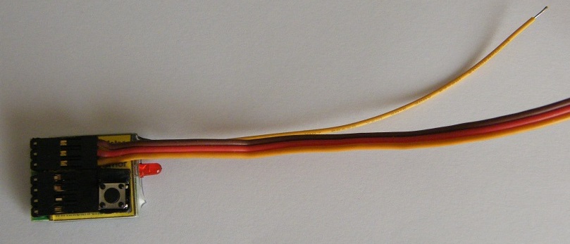
The new
Compact timer with connector pins over the pc board and a single
pushbutton switch to start and stop the flight.
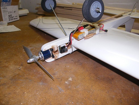
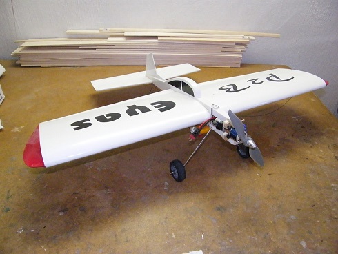
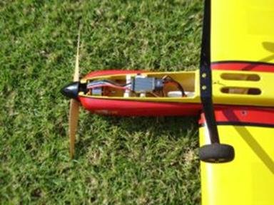
This works very well on small models especially profile stunters, as
you can see from the conversion of a Lanyu P2B trainer below.
I also have new firmware that allows lower rpm down to 4300 rpm if you
need to use this timer on models with big, slow revving propellers.
Please contact me for local prices or one of my international agents for the price in their country.
|
KR
Governor Timer System |
|
|
KR
Governor Timer ver. 2 V |
|
|
KR
Governor Timer ver. 2 H |
|
|
KR
Governor Timer Compact |
|
|
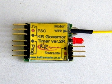
KR
Governor Timer ver. 2 R |
|
|
Programming
Card ver. 2 |
|
|
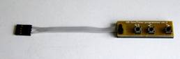
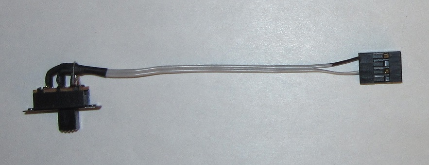
Standard
switch |
 |
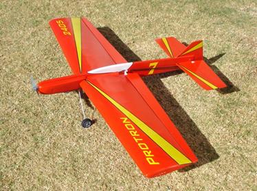
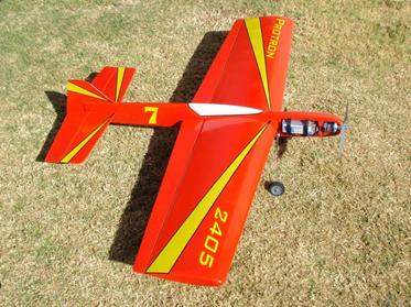
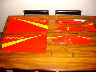
My Protron take-apart electric stunter
Peter Locke’s 40 Watt electric stunter
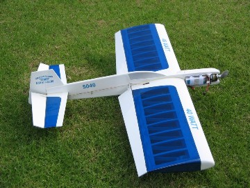
Peter Locke from Grahamstown’s 40 Watt electric stunter shown above, uses my 40 size Plug n’ Play package with a 4-cell 2200 mAh Lipo battery. This neatly built model is basically a modified Eze-Pro stunter. The ESC and timer are inside the cheek cowl.
IF you would like to build and electric version of the Eze-Pro, then here is the link to download the plans> Electric Eze-Pro plan
About Electric Control line Stunt

Updated Electron to make it lighter Electron nose with MVVS 6,5/910 motor
Electric powered models have now started to be used successfully in C/L models, mainly in stunt. This quiet revolution has all but taken over in R/C pattern at the top level. Prices of batteries, motors, and ESC’s (Electronic Speed Controllers) are now at the level where it costs around the same as flying glow engines. The battery technology has already been improved to allow for over 200 good flights from around the 50 or 60 of a few years ago. I predict (it is now July 2010) that within a year or so, it will be cheaper to fly electric than glow.
To use electric power in C/L, it is necessary to add a timer/throttle pulse generator in place of the R/C receiver. This timer provides a delay for the start-up to allow you to walk out and pick the handle, the time for the actual flight, and also the right amount of throttle signal for the speed to fly. The better (and more expensive) ESC’s usually have a governor mode that keeps the rpm constant independent of the load on the propeller. The governors available are mostly designed for 3-D aerobatic helicopters, so they are not always suitable for stunt C/L.
Why do you really need a governor? Because when you want to fly a decent stunt pattern, you do not want the speed to drop when you climb, and most certainly do not want extra speed when you diving at the ground! It’s also not just because the load varies all the time, it's also because the battery voltage also drops down as you fly. With R/C models this is not as noticeable because the pilots throttle back the power regularly. With a C/L stunter, you need to run at around 90 to 95% power for 5 to 6 minutes, and the voltage drop is really noticeable.
Glow engines have similar problems when the load changes during manoeuvres, and this is why it has always been a problem to find a decent stunt engine that behaves well through the pattern. Tuned pipe systems, 4-strokes and even diesels have all been used to get a good engine run, with varying success through the years. I have tried all of these systems and I can state categorically, that no engine system works as well overall as electric power….BUT…..and there is always a “BUT”……you need to use a good governor system to keep the rpm constant. There are timers available that add power over time to compensate for the voltage drop, but they still have the problem of losing speed in the climbs and speeding up in the dives. In wind, they also tend to wind up in the manoeuvres like the loops.
There are only a few ESC’s with good governors in them plus the propeller brake feature, and they are expensive. I therefore developed a timer over a two year period that monitors the rpm of the motor and uses this data to keep the rpm constant all the time. It uses one extra wire that must be connected to any one of the motor wires and this is the only extra thing to do. So now, it’s possible to use most low-cost ESC’s that do not have built-in governors, to fly at a solid constant rpm. This timer costs about the same as most of the commercially available basic timers but does the work of a good governor as well as the normal timer functions. This particular timer is the KR Governor Timer and here are all of the features:
Features:
New variable and differential governor gain for extra power in climbs and hard corners!
Works on the majority of basic ESC’s without governor software
20 MHz crystal clock for very fine rpm adjustment and stability
When setting the rpm, it is set in actual governor mode, and will run up to the last programmed rpm each time. It can therefore be set without a tachometer if necessary
In-flight indication of time-out with 2 seconds of slow rpm and then extra power for a few seconds for that great landing
Motor shuts down if the rpm drops too far below your set rpm
Motor shuts down if the propeller is jammed for any reason
Specifications:
RPM range: 7500 to over 12000
Voltage: 3.3 to 5.5 volts (max 6.0 volts)
Weight: 3.5 grams (7.0 grams with slide switch unit)
Size: 25 x 30 mm (pc board size)
Exciting
news! I found a way with software alone (no
external devices) to add power in the hard corners and climbs. It works by
adding governor gain in one direction only, and this is when the system is
loaded as in a hard corner or climb. The standard gain factor is 1 and now
this is user adjustable from 1 to 7 by using the same programming card.
This is explained more below under “Setting the Gain.” Now it is possible
to slow down the lap times and still have plenty of power to fly the
pattern. This is a giant step forward in electric stunt! A good solid
governed constant rpm is a great thing to have, but many find the faster
lap times a little disconcerting. To have a little extra boost in the hard
corners and climbs is a lot better. So far everyone that has tested it is
very excited.
As you can see from these features, it has the added benefit of being able to shut down the motor if the rpm drops below a preset amount. What has happened to me on occasions, is that the battery voltage drops before the timer times out, and the low rpm trigger point shuts down the motor. Please be aware of this and check your batteries carefully. Most ESC’s these days do have a low voltage cut-out point, so set this to the high option that is usually 3.2 volts, and then set the sut off option to slow down rather than stop immediately. This can happen due to a bad charge or even forgetting that you have not charged the battery etc. Shutting down the motor will help to save your battery. The other important point to this is that if the prop gets jammed like in a crash or a nose-over on the take-off, then this may just help to prevent your ESC burning out……..ask me how I know this!!
How well does the governor work? Here below is a chart recorded on my Eagle Tree data recorder.
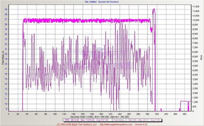
As you can see, the rpm stays very constant with the varying load. You can also see the dip at the end when the motor runs slowly for 2 seconds, and then goes full power for the last 5 seconds.
Troubleshooting: I have now sold many of these timers and the general feedback is very good, but there are a few customers that have experienced difficulties. I have found that the problems are due to four basic reasons:
The first problem has been with ESC’s that have a BEC (Battery Eliminator Circuit) regulator voltage of more than 6.0 volts. This will destroy the processor chip on the timer pc board! The majority of ESC’s have a 5.0 volts output, so please use this setting. With the use of LIPO and LIFE receiver battery packs these days, some ESC’s are using an output of 6, 5 volts or even more. Please check this carefully!
The second problem is due to using ESC’s that have been set to a particular throttle range previously to suit other systems and timers. My timer has a throttle pulse width of 1.0 ms (milliseconds) and a maximum of 2.0 ms. If your ESC will not initialize properly on connecting the battery with the correct beeps, then it may be that it needs calibrating to the timer. There is a section below (Using the KR Governor Timer) that explains exactly how to do this.
The third problem occurs when using the timer in a range below its design limit of 7500 rpm. It is necessary to find a motor/propeller combination to keep the rpm above this limit. I do have another version of the program that will work down to 4300 rpm but then this lowers the upper limit as well. This was done to cater for the low revving big props on indoor models.
The fourth problem could be due to setting the slow startup feature on the esc. This is used on model helicopters to prevent damage to the gearbox, and will cause the governor timer to stop the motor as it ramps up to governor mode. Please disable this feature on your esc. The timer has it's own soft startup feature.
Using the KR Governor Timer
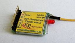
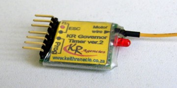
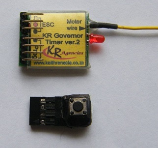
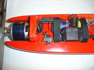
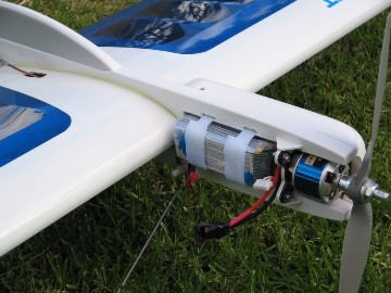
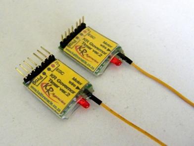
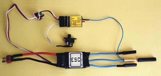
I make two versions of the timer at present, and if you look at the photos below, you’ll see that you can have one with vertical pin connectors and the other with horizontal, or in-line pin connectors. The vertical pin version is better suited to the built-up fuselage models and the horizontal one works better with profile models, but this is obviously up to your personal preferences. The picture on the right shows how it is all wired for flying. You can see how the extra wire is soldered to one of the motor wire bullet connectors on the ESC. I do add a piece of heat-shrink tubing in the package to neaten it all up and insulate the connection.
Notice that there are
no pushbuttons or switches on the actual pc board. I make the switch work
on a remote lead. After trying many pc boards with buttons and switches, I
always found it difficult to mount the unit so that I could get to the
switch, especially on full-body models. There is another good reason for
the slide switch, and that is to allow programming of those ESC’s that
need to have the throttle range set before using them. This normally
requires the use of an R/C transmitter and receiver, because the ESC needs
to be set for maximum and minimum throttle. Many times C/L people do not
have an R/C system, so this is a “nice-to-have” for them. You simply
slide the switch to the ON position (when the switch lever is above the
two wires that are connected to it) and connect the battery. This gives
full throttle to the ESC. The motor will not start up because all of the
ESC’s are programmed so that they will not run the motor if you have the
throttle fully open and switch on the power. You then switch the timer
slide switch to the OFF position and the throttle range is set. You only
need to do this once normally. The ESC manuals will explain how many beeps
to listen for etc.
This system was designed with the sport flier in mind, especially those that are “non-technically inclined” and do not want to get involved with having to buy a laptop or use a computer to program the system. There are no codes to remember and you will not need to become a computer programmer either! Besides the plug-in switch being convenient, remember that if you need more timers for other models, then you just need to have one programming card. You can then order the timer on its own, saving you money!
Programming the KR Governor Timer
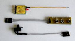
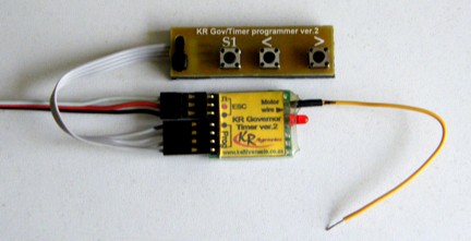
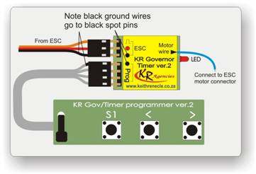
The photos and diagrams below show the programming card and how it is fitted. Please make sure that you connect the plugs the right way around as shown below. You will also need to connect the ESC to the timer using the 3-pin connector. Most ESC’s need the motor to be connected as well, or they will be damaged, so please be careful of the spinning propeller, and always have someone hold the model while you are setting the program.
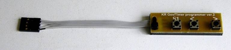
To program the timer, remove the slide switch (if it is connected) and plug in the programming card using the 4-pin connector.
Setting the rpm:
Press S1 twice quickly and release. The LED will flash twice and stay OFF to tell you that you are in the Set RPM mode. The motor will start running up to the last set rpm, and will be in governor mode. Use the “>” button to increase the rpm and the “<” button to decrease the rpm. Each press and release will add or subtract approximately 50~100 rpm, depending on the number of poles in the motor. Press S1 to store the rpm (this is something that is sometimes missed), the motor will stop, and the LED will go back ON.
Each press is approximately equal to 100 rpm, and this is the standard resolution for most tachometers. This is easier than setting a needle valve on an engine! In fact, if you don’t own a rev-counter or tachometer, this can be done by listening for the increase or decrease and storing the revs. I have tried to make using this system as close as possible to using an engine, so you can set the revs to where it sounds about right, and fly the model using a short flight time. If it’s wrong, then simply increase or decrease the rpm for the next flight. There’s no need to change propellers if you are using the recommended size and pitch for the particular model. Of course, this sort of flexibility allows you to experiment to your heart’s content without having to change head-shims, venturi’s, nitro content etc. etc.
An important point to remember is that for any governor system to work, there needs to be some reserve power, or what is called “headroom.” It is no good to run the system flat out, or at full power, because there will be no reserve power when the motor is loaded more than this will allow. If you keep pressing “>” button in while setting the rpm until the rpm no longer increases, then you will be at the maximum rpm that the system will operate in. I have allowed for some reserve at this setting so this no problem at all, but it will be the maximum rpm that your particular system is capable of. Just remember to use a good, freshly charged battery to set the rpm to it’s allowable maximum.
It is equally important to remember that a motor for stunt needs to be operated at around 85 to 90% of the full throttle setting. If you find that the correct rpm is around the 50% throttle mark, for example, you are using the wrong motor/prop/battery combination. This will not be an efficient set-up for the motor, and you will most likely overload the ESC as well. A good indication of this on some of the esc’s, is that you will get the motor governor hunting back and forth if the rpm is too low.
Note: The < and > buttons are only used to set the rpm, and do not work for setting flight or delay times.
Setting the flight time:
Press the S1 button 3 times and release. Please note that for simplicity, I have programmed this for steps of 10 seconds. You certainly do not need a finer timing for shutting down the motor at the end of the flight. If you consider the engine set-ups, then it could be to the nearest minute or two! After pressing S1 3 times, the LED will flash 3 times to indicate that you are in the flight time setting mode. You then hold the S1 button in, the LED will flash, and you simply count the flashes for each 10 second step. For example, if you want a flight time of 5 minutes, then you need to count 30 flashes, (30 x 10 = 300 seconds = 5 minutes). When you release the button for more than 2 seconds, the setting is automatically stored. If you press S1 before the 3 seconds the counting will continue. Please not that if you enter this mode, and do not press S1 within 3 seconds then a 10 second flight time will be stored. Of course, to correct this, simple do the process over again and store the desired time.
One more point on the flight time. Although the flight time allowed in competitions is 7 minutes (8 for AMA rules), when you fly at a constant rpm, the lap times will be a little faster, and normally, the entire pattern will be completed in close to 5 minutes. I find that a comfortable time is 5 minutes 30 seconds, or 330 seconds. Much of the flight time is wasted when you fly with engines. Sometimes this is a minute or more. Such a waste!!
Setting the start-up delay:
Press the S1 button 4 times and release. The start-up delay is the delay time that occurs after you switch the slide switch on to start the flight. The timer is pre-programmed with a 25 second delay, so if this suits you then leave it as it is. After the 4 presses of S1 then the LED will flash 4 times and then go off. Hold in the S1 button as before and each flash counts as one second. Letting go the S1 button for more than 3 seconds will automatically store the setting. Please not that if you enter this mode, and do not press S1 within 3 seconds then a 1 second start-up delay time will be stored. Once again….BEWARE the spinning propeller!
Setting the governor gain:
Press S1 five times quickly and release. The LED will flash 5 times and stay OFF. Now hold in the S1 button and count the number of flashes from the LED. Each flash adds 1 to the gain setting to a maximum of 7. If you release S1 for 3 seconds, then the gain is automatically stored. The LED will flash 5 times and the stay on to indicate this. If you do count more than the maximum of 7 flashes, then the maximum amount remains at 7. The default setting that the timer comes with is 4. If you do enter the gain part of the program and fail to press the S1 button, then the program will store a setting of 1 after the LED flashes 5 times again.
Disconnect the battery when the settings are right.
Flying with the Governor Timer

Plug in the esc and slide switch as shown in the above picture. Make sure that the slide switch is in the OFF position. The ON and OFF positions are illustrated below. Connect the battery, and if you find that the slide switch is in the ON position, just switch it OFF again. You do not have to disconnect the battery as it will simple set the throttle range when you do this. If you get it all wrong and your ESC starts producing warning beeps from the motor, then disconnect the battery and start over.

When you are ready to start, then switch the slide switch to the ON position. After a short time (+/- 1 second) the motor will spin the propeller slowly for 2 seconds. This indicates that the timer is now in the short start-up delay period. After the set time (default = 25 seconds) the motor will start up slowly at first, and then go to the set rpm in governor mode. This will continue until the flight time is over. Note that the programmed time, starts with the slide switch being turned on, and runs at this governed rpm until the end of your set time. After this, the motor will run slower for 2 secs and then go to full un-governed power for 5 seconds. This will allow you to make that perfect landing. For a better glide, you should enable the brake in the ESC so that the free-wheeling propeller can stop. This is important in FAI competitions. See the manual for your ESC to set the brake mode.
If you do have any questions or suggestions then please let me know. I continually strive to improve my products, so your feedback is invaluable to me. All of my contact details are in the page marked “Contact us” on the left in the index.

My 1st Electron at 2008 world champs in France